Background
For decades, the "accuracy" of a technical drawing has
been judged by the ease of manufacture and assembly of the component. If the final product
was satisfactory then the drawing describing the component was "accurate". While
ever paper drawings have been the basis for manufacture the actual geometrical accuracy
has been of secondary importance.
Today 3D models are used directly for production. Data is
transferred from the design system to the machining system. In some cases no drawings are
generated - accuracy is fine if the final result of production and assembly is good. In
this case the dimensions could be "irrational" - for example 24.7513244423mm -
the important thing is that the components fit together.
If however, 2D drawings are used in the manufacture of components
then the dimensions should, ideally, be "rational" for example 24.75mm. This way
it will be much easier to manage the design and production processes. Designers will be
able to communicate dimensions verbally. Relationships between components (e.g.
clearances) can be considered without being concerned about the "unseen"
decimals. 2D-drawings sent electronically (2D-dxf,iges) should contain only rational
dimensions as CNC systems work slavishly with an accuracy greater than that our drawing
standards anticipated.
CAD systems allow dimensioning to a specified number of decimal
places, 2 is quite common. If a vector with a length 24.7513244423mm is dimensioned it
will show 24.75(mm). The system will probably not inform the user that the geometry is in
fact 0.0013244423mm longer!
CAD systems help the user to work accurately, but if an error
does occur then it will tend to spread into other areas like a virus. Many hours of
detective work must be spent if the original error is to be found. If the error is
critical and the cause cannot be found then it must be compensated for elsewhere.
The Accuracy Advisor can help in finding geometrical and
dimensional errors (anomalies). If a dimension is incorrect and the geometry does not
correspond exactly the user may adjust the geometry. The Accuracy Advisor allows easy
access to geometric data (length, radius etc,) and highlights the grades of elements
accuracy found in the drawing.
At the time of writing only the decimal format of dimensions is
supported. Feet, inch and fractions are not suitable for dimensional analysis.
Definition of
"accuracy"
ME10 does a very good job of managing fundamental geometric
accuracy. Under normal conditions it works to 13 decimal places! On the other hand an ME10
user can be very poor in exploiting this! Errors can be made in selecting the
points for a rotation; values can be obtained manually with a calculator or the cursor can
merely catch the wrong points. It is not uncommon that errors of 0.001mm occur.
Accuracy Advisor looks at the length of lines and the
radius/diameter of circles, arcs and fillets. The user can define to which level of
accuracy these elements should be compared. The most important feature though is the
ability to analyse dimension's displayed value against the geometry it describes. It is
this difference which gives the "error". If a dimension shows 32.76 but the
geometry measures 32.7610867856 then the error is 0.0010867856mm.
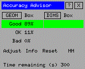
Accuracy Advisor deals with three levels of accuracy: GOOD, OK
and BAD. The table below illustrates how the Advisor decides which level an element should
be given.
| |
Geometry |
Dimensions |
GOOD
(green) |
Lines:120.25 Arcs /Circles: 24.334 |
Dim:
"17.731" Geom.: 17.731 |
OK
*
(cyan) |
Lines:
120.2500000000001 Arcs/Circles: 24.3339999999998 |
Dim:
"17.73" Geom.: 17.7299999999999 |
BAD
(red) |
Lines: 120.251 Arcs/Circles: 24.3345 |
Dim:
"17.73" Geom.: 17.7305437 |
*) Note: Some geometry with "rational" lengths may be
classified as "OK" when they are actually "GOOD".
You are Accuracy Advisor User number: